Waveforms of Therapeutic Currents: Difference between revisions
Rachael Lowe (talk | contribs) mNo edit summary |
Rachael Lowe (talk | contribs) mNo edit summary |
||
| Line 4: | Line 4: | ||
== Fundamental Terms == | == Fundamental Terms == | ||
=== | === Oscilloscope === | ||
An ossiloscope is an instrument which is used to observe voltage changes during time in electric circuits. | An ossiloscope is an instrument which is used to observe voltage changes during time in electric circuits. | ||
Revision as of 11:31, 18 October 2017
Waveforms of Therapeutic Currents[edit | edit source]
Therapeutic currents are, special electric currents that are applied to human body for healing the body. Generally these are defined by using voltage-time chart of the current which can be seen in the oscilloscope screen. In this page I will summaries the waveform of common therapeutic currents.
Fundamental Terms[edit | edit source]
Oscilloscope[edit | edit source]
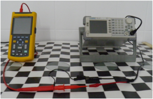
An ossiloscope is an instrument which is used to observe voltage changes during time in electric circuits.
Signal Generator[edit | edit source]
A signal generator is an instrument which generates electrical signals at given waveform, frequency and amplitude. Electrotherapy equipment is a kind of signal generator which generates therapeutic signal waveforms in safe frequency and amplitude.
Frequency[edit | edit source]
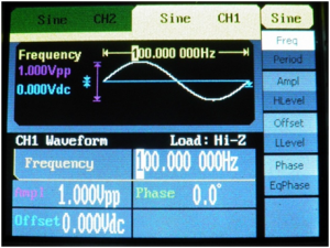
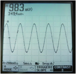
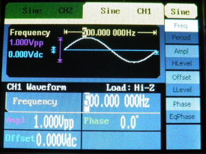
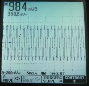
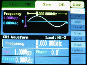
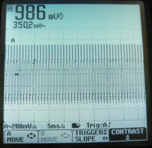
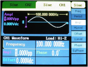
Frequency is a term which describes how many times a waveform repeat it self per second by signal generator.
A 100 Hz Sine Wave[edit | edit source]
A 500 Hz Sine Wave[edit | edit source]
A 1000 Hz Sine Wave[edit | edit source]
Peak Amplitude[edit | edit source]
The term peak amplitude defines the highest positive or negative value of a waveform. In therapeutic currents peak amplitude generally defines the highest value of the voltage during time.
Peak to Peak Amplitude[edit | edit source]
The term peak to peak amplitude defines the amplitude between the highest negative to highest positive value. Peak to peak amplitude of a sine wave is equal to two times peak value of a sine wave.
Mean Amplitude[edit | edit source]
The term mean amplitude defines mean value of a waveform. In therapeutic currents mean amplitude is a quantity in terms of voltage. Peak amplitude of a sine wave has different mean amplitude value. Mean amplitude of a sine wave is equal to 0.637 x Peak Amplitude.
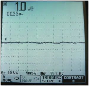
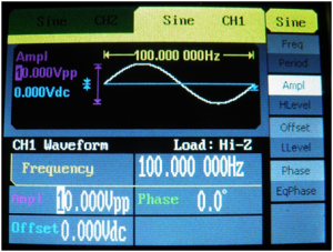
Peak and Mean Amplitude of 100 Hz and 1 Volt Sine Wave[edit | edit source]
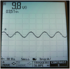
Peak and Mean Amplitude of 1000 Hz (1KHz) and 10 Volt Sine Wave
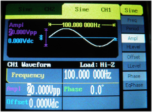
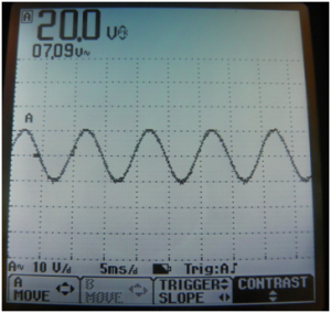
Peak and Mean Amplitude of 1000 Hz (1KHz) and 20 Volt Sine Wave
Square Waveform[edit | edit source]
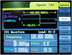
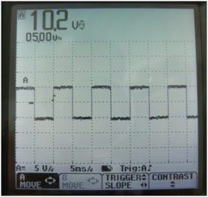
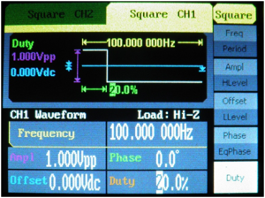
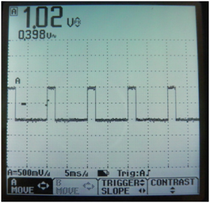
Square waveform is a common therapeutic waveform. Interrupted galvanic current and TENS are forms of Square waveform. The main parameter of a square waveform is duty cycle. It defines the time ratio when voltage is higher or lower then zero and when voltage is equivalent to zero.
