Lower Limb Prosthetic Introduction
Original Editor - Francois Friedel, Hmayak Tarakhchyan and Sarah Evans as part of the WCPT Network for Amputee Rehabilitation Project
Top Contributors - Admin, Tarina van der Stockt, Tony Lowe, Naomi O'Reilly, Kim Jackson, Rachael Lowe, Simisola Ajeyalemi, Amrita Patro and Amanda Ager
Physiotherapy and Prosthetics[edit | edit source]
The Physiotherapist spends many hours with the patient with limb loss during the rehabilitation phase. For the patient’s best interest the physiotherapist and prosthetist should work closely together. Therapists are urged to obtain the manufacturer's information regarding the prosthetic components of the patient that is treated. [1]
The Physiotherapist is not required to understand all the technical aspects of the prosthesis and fitting but should have a knowledge of the following: [1]
- Proper prosthetic fit and alignment - this will enable the therapist to to evaluate if the cause for gait deviation and pain is as a result of the prosthesis. [2]
- Function of the different prosthetic components - to be able to teach the patient to use the prosthesis optimally and to apply the correct gait training strategy (see for e.g. different types of knees), and avoid pitfalls (for e.g. loading the prosthetic toe might unlock a specific knee joint). [2]
- Correct donning of the prosthesis and what to do if the socket sits uncomfortably. [2]
Prosthetic Prescription[edit | edit source]
Prescription of a prosthetic is a multidisciplinary process that includes at least the user, prosthetist and physiotherapist. During the prescription process the team decides on the type of device that should be fabricated and also the socket design, the various types of components and the choice of suspension. All these decisions are very important for the rehabilitation process that will happen later.
Fabrication of the Prosthesis[edit | edit source]
The fabrication of the prescribed prosthesis also goes through various stages that could influence considerably the rehabilitation and the physiotherapy program planned after the first fitting.
These fabrication steps are:
- Casting
- Positive mould
- Rectification
- Assembling
- Alignments
- Cosmetic
Prosthetic Components[edit | edit source]
Replacing the movements of the human body with prosthetic components is a very complex and complicated task. Prosthetic components can imitate, with different level of complexity, these movements but never replace them. Obviously, the higher the level of imitation, the higher is its complexity and price.
With loss of sensory and proprioception, the amputee must rely solely on sensory capabilities of his stump and body, which may affect confidence during the execution of the march.
However, modern prosthetic technologies offer wide range of components, especially in lower limb prosthesis, which manage to replace the major movements and enable users to perform the gait.
Below, we add some examples of common prosthetic components and correlation between the prosthetic design and the gait.
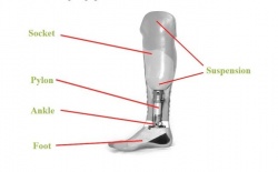
TT prosthetic components
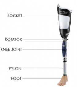
TF prosthetic components


1. The Socket (Casting, Positive Mould, and Rectification)[edit | edit source]
The prosthetic socket is the primary interface between the amputee's residual limb and the ground and therefore a good, comfortable fit is required to ensure a positive outcome is reached in an amputees rehabilitation[4].
The prosthetist takes the measurements for the socket using plaster bandages to create a cast (Casting). The cast created is filled with plaster powder to create a positive mould (Positive Mould). The positive mould is then modified to optimize the socket fit, this process is called “rectification” (Rectification). The socket is then shaped over the mold to create the custom socket, this is referred to as a laminated socket. A “check”/diagnostic socket is sometimes fabricated before creating the definitive socket (this socket is usually transparent, allowing the clinician a complete view to evaluate the fit and make changes). Multiple fittings are at times necessary to assure the best possible design with a comfortable and effective fit. Generally sockets are made out of plastic, either thermoplastic or with thermosetting, called laminated sockets. Laminated sockets can be reinforced with fibre glass, carbon fibre, or nylon[1].
Because it is the interface between the device and residual limb, the quality of the socket design, whatever the model used, is key and decides on user’s comfort and his/her ability to control the appliance. A user will never walk properly and will never reach the agreed goal of the rehabilitation plan if the quality of the socket fit is not satisfactory regardless of the material used (plastic, resin or carbon). The quality of the fit depends entirely on the work of the prosthetist and his/her capacity to insure precise measurements during casting and suitable rectification of the positive mould to distribute forces over the socket where needed.
Other methods:[edit | edit source]
- Polypropylene technology developed by the International Committee of the Red Cross (ICRC) is used in prosthetics all over the world, especially in resource-limited countries and projects by the ICRC.
- The Modular Socket System developed by Ossur can be used to make a socket directly on the patient's residual limb. It is an easier and quicker process but the cost is higher. Delivery time to the patient could be within one day. [7]
- A more sophisticated and expensive technique utilized today is a CAD system (Computer Aided Design). With the improvement of technology 3D printed sockets are also gaining momentum.
Pressure tolerant and pressure sensitive areas:[edit | edit source]
The prosthesis applies forces over the body. The amount, the location of their application and the means that control those forces contributes to the impact the prosthesis has on mobility, function, and acceptance of the device. Pressure distribution over a greater surface diminishes the load and provides more comfort during the use of prosthesis.
Although the majority of the stump areas are considered as pressure tolerant, some are very sensitive and cannot support any pressure.

Attention:
Very short TT stumps (shorter than 20% of the anatomical length) are insufficient for providing adequate control over the prosthesis and supporting the body weight. Nevertheless, the quality of the stump is more important than its length.

It is obvious that to be able to fit the stump into the prosthesis: taking into consideration all those preconditions mentioned before, it will be necessary to count on the principal element of the prosthesis – the socket. The later serves as an interface between user and device and due to that has to respond to the physical-anatomical demands of the patient, to the mechanical specificities of components and to the biomechanical requirements of the gait.
Below we describe some common TT and TF socket designs.
Sockets TT[edit | edit source]
Patellar Tendon Bearing
| Socket PTB (Patellar Tendon Bearing)
The weight bearing takes place below the patella, at the patellar tendon. The suspension is generated by a belt that is tightened around the distal part of the thigh. The tension of that belt limits the blood and lymphatic circulation; moreover, after long term use results in muscle atrophy and other related problems. |
 |
| Socket PTB SC (Patellar Tendon Bearing Supracondylar)
The weight bearing takes place below the patella, at the patellar tendon. The suspension is generated at the medial and lateral areas of the femoral condyles. Compared to the PTB socket with belt suspension, this design does not produce problems of blood circulation or atrophy. For the moment, this type is used worldwide as most basic design for prosthetic fitting of medium and long stumps. |
 |
| Socket PTB SC SP (Patellar Tendon Bearing Supracondylar Suprapatellar)
The weight bearing takes place below the patella, at the patellar tendon. The suspension is generated at the medial and lateral areas of the femoral condyles and at teh suprapatelar area. This type is indicated for short stumps, as well as in cases of antero-posterior instability in the knee. |
 |
Indications
Primary Amputees - The PTB socket is good for primary amputees as the socket can be modified to accommodate the changes in the residual limb that occur for 12-18 months after the amputation.
- Sensitive Residual Limbs - If the amputee has a particular area of sensitivity on their residuum it is possible in a PTB socket to relieve these areas more easily than in a total surface bearing style socket.
- Bulbous Residual Limbs - The construction of a PTB socket, an inner liner and outer hard socket, allows for build-ups to be applied to the inner liner allowing easier donning and doffing for an amputee with a bulbous residual limb
- Poor Hand Dexterity/ Poor Eyesight/ Hemiparesis - PTB sockets are much easier to don/doff than total surface bearing sockets
Contraindications
- Active amputees can find the PTB trim lines and suspension methods too restrictive, especially with regards to knee flexion.
- Some amputees can find the PTB prosthesis pistons (see pistoning in gait deviations)
- Some amputees cannot tolerate the pressure on their patella tendon required for a PTB prosthesis to work effectively.
Total surface bearing sockets
| Socket SSS (Silicon Suction Socket)
The weight bearing takes place all over the stump surface. The suspension is generated by means of tight adhesion/friction between stump and silicon liner that has a pin at its distal part. This pin is installed in a blocking mechanism inside the prosthetic components, or using a suction mechanism, hence insuring the suspension. Indicated for all types of stumps. |
 |
- TSB sockets “uniformly distribute weight over the entire residual limb” which therefore “delivers a minimal skin pressure”[10].
- TSB sockets are volume matched to the residual limb with 100% surface contact during the gait cycle.
- Successful fitting of a TSB socket requires good control of the soft tissues, minimised pressure peaks and distribution of load over the maximum surface area available[11].
Advantages and Indications
- Active amputees benefit from the lower trim lines possible with the TSB style design[10][12] .
- TSB sockets reduce pistoning of the socket (see pistoning in gait deviations) on the residual limb by providing total contact throughout the gait cycle[13]
- Proprioception is increased due to weight bearing over the entire residual limb and good pressure distribution by the socket walls, which in turn enables the amputee to have better balance with eyes open or closed[13]
- Suspension of the TSB socket is also noted to be better than the PTB design as it is integrated in the socket using locking pins or suction[13].
- Due to the entire surface of the residual limb accepting weight in the TSB socket it is believed that these sockets are more comfortable because overall socket pressure is reduced[14].
Disadvantages and Contraindications
- TSB sockets are not suitable for primary amputees due to volume changes in the first 12-18 months post-amputation[15]. For the same reason TSB sockets are also not suitable for amputees undergoing treatments such as dialysis due to volume fluctuation
- Unsuitable for patients with short residual limbs, less then 10cm long, which require higher trim lines for stability around the knee[12].
- Some amputees may experience pain at the distal end of their residual limb due to the way a TSB/HST socket weight bears over the entire limb[15]. Also patients with excessive soft tissue may drop down into a TSB/HST socket too much which will cause pain at the distal end[15]. Amputees with bony spurs are also not suitable for TSB/HST sockets[15].
- Discomfort during knee flexion may result due to the silicon liner bunching up in the popliteal region[16]
- Increased perspiration may result due to the silicon liner, which can lead to irritation of the residual limb[16]
- TSB/HST sockets are not indicated for amputees with visual/sensory disturbances or Hemiparesis as they are more difficult to don/doff than a PTB design[15].
- Amputees with excessive soft tissue may find they get discomfort upon knee flexion due to creasing of the silicon liner[15]
Transversal view shows the differences between the internal shapes of PTB SC v SSS sockets.
| Socket PTB SC | Socket SSS |
 |
 |
Sockets TF[edit | edit source]
For TF sockets, the designs mostly used at present are the followings.
Quadrilateral Socket
The weight bearing takes place at the ischial tuberosity by the means of ischial support at the posterior shelf of the socket. The suspension is provided by negative pressure (suction) that is generated by adequate fitting of the socket over the stump. In some cases, the suction suspension can be complemented by the use of the belts (Silesian, Neopren, etc.).
For the moment, this type of socket is in most use for all types of stumps.
| Transversal view | Medial view | Posterior view |
 | ||
Ischial Containment Socket
The weight bearing takes place all over the surface of the stump without localizing one specific point; hence, generating more comfort, better control over the prosthesis and security for the user. The ischial tuberosity does not suffer from direct, complete and permanent weight bearing. The principal pecularity of this design, apart of the exact volume determination, is the medial wall/border of the socket that contains the ischial ramus. The suspension is provided by negative pressure (suction) generated by adequate fitting of the socket over the stump.
For the moment, this type of socket is in worldwide promotion, replacing the quadrilateral one.
Transversal view Medial view Posterior view
| Transversal view | Medial view | Posterior view |
 | ||
The Assembling / Alignment[edit | edit source]
Once the socket fits comfortably, the foot, knee (if necessary) and other components are then attached to the socket (Assembling). The alignment process starts in order to insure appropriate function and respect of biomechanical structure of the body (Alignment).
As the socket fit, a proper alignment and biomechanical adjustment of the prosthesis to the user is crucial and needs time and expertise in order to provide the best functional outcome for the user.
Initial “Bench” Alignment,[edit | edit source]
Done on the bench without the user. The alignment parameters depend on the socket design, the types of components used and the style of shoe (the height of the heel is very important). It follows technical instructions provided with the technology selected. The use of an alignment jig is highly recommended in order to attach the socket to the rest of the prosthetic leg at the optimal place.
Watch the following presentations to learn more about transfemoral and transtibial initial alignment (use the pause button to examine each slide)
Static Alignment[edit | edit source]
Done during the first fitting session with the user and a multidisciplinary medical team. This alignment is done in sitting and in standing position while patient is placing weight on the prosthesis. The aim of the static alignment process is to make all necessary corrections in height, inclination and translation to adjust the prosthesis to the specific biomechanical profile of the user before the first step.
Watch the following presentations to learn more about transfemoral and transtibial static alignment (use the pause button to examine each slide)
Dynamic Alignment[edit | edit source]
Done within gait training and while the user is walking. The dynamic alignment is implementation with a particular user of the generic gait deviations analysis.
Watch the transtibial dynamic alignment presentation (use the pause button to examine each slide)
2. Prosthetic Feet[edit | edit source]
Prosthetic feet can be made from wood, rubber, urethane, titanium, graphite and carbon fibre. They can be lightweight, energy-storing, or dynamic and some can allow adjustability of heel height. All prosthetic feet should provide passive plantar flexion in early stance, neutral position in mid stance and toe hyperextension in late stance
Among different designs of feet it is worth mentioning those most common in use.
Non Articulated Feet[edit | edit source]
Generally known as SACH (Solid Ankle Cushion Heel) feet and consist of a rigid feet without ankle articulation, where the heel absorbs the shock and the forefoot simulates the dorsal flexion of the foot. There are feet with different degrees of heel amortization offered in the market.
In spite of having a very simple design, SACH feet respond to functional necessities in all the phases of the gait.
Can be used for regular prosthetic treatment of the majority of amputees and/or the initial fitting before proceeding to more sophisticated foot design.
 |
 |
Articulated Feet[edit | edit source]
They can be with certain range of liberty in only saggital plane to simulate movements of planter- and dorsi-flexion, or in saggital and frontal planes to simulate planter- and dorsi-flexion as well as pronation and supination. There are feet with different degrees of amortization of all those movements.
The advantage of imitating the anatomical movements of the ankle is not only for cosmetic reasons but also for a functional one: after the heel contact, the immediate forefoot contact occurs, promoting the ground reaction forces that secure the prosthetic knee in extension.
Can be used for regular prosthetic treatment of the majority of amputees, in particular for TF amputees.
 |
 |
Feet with Energy Return[edit | edit source]
The basic element of these feet is the design of the keel that simulates a spring molded carbon fiber plates. This design has better energy response during the toe-off phase (imitating the natural impulse of the foot) by means of the shape and the material of the keel.
Can be used for regular prosthetic treatment of the majority of amputees, in particular for those with intermediate activity level.
 |
 |
(Views without cosmetic cover)
3. Prosthetic Knees[edit | edit source]
The majority of the prosthetic knees used worldwide can be divided in two groups depending on the number of axes.
Uniaxial Knees[edit | edit source]
During the flexion/extension these articulations execute a simple rotation around the knee axis. They are of simple design and their easy alignment responds to the rules of mechanics.
There are exoskeletal and endoskeletal knees, both versions can have manual or automatic blocking of the flexion to be used in users with poor muscle power.
The knees without blocking can be used for regular prosthetic fitting of amputees with adequate muscle control and/or in situations of limited economic resources.
 |
 |
Poly-axial Knees[edit | edit source]
Based on principle of two or more axes of articulation. Knees of the most frequent use are of 4 axes (or 4 bars). Without giving importance to the number of axes, the knees of poly-axial design have one thing in common - the Instant Centre of Rotation (ICR) is situated much higher and posterior than the mechanical axes when the knee is in extension.
To localize the ICR of a polycentric knee, we need to extend virtually the center lines of the lateral bars towards proximal - the intersection of those lines will indicate the ICR. This causes a high level of stability in the knee against involuntary flexion during the heel strike.

The Cosmetic[edit | edit source]
When the socket and the alignments are fine, and when the user reaches the end of his rehabilitation program and can successfully do all exercises and activities proposed in the treatment plan, the multidisciplinary team can decide to finish the prosthesis. That generally means to fix all adjustments of the device and make the cosmetic. The cosmetic may be very different depending on user’s tastes and needs. A sportive kid may like a prosthesis with bright colors. A lady may prefer a texture and color that best imitates their real leg to be able to wear dresses. And a farmer working in a wet environment would choose a plastic waterproof cosmetic.
The choice of cosmetic, as the choice of components and technology, will also depend on the financial resources and the level of medical coverage allocated to the fabrication of the device. Prices are very different and is a factor to take in consideration.
References[edit | edit source]
- ↑ 1.0 1.1 1.2 Engstrom B, Van de Ven C, editors. Therapy for amputees. Elsevier Health Sciences; 1999.
- ↑ 2.0 2.1 2.2 Prosthetics. AustPar. Australian Physiotherapists in Amputee Rehabilitation. Available from: http://www.austpar.com/portals/prosthetics/prosthetics.php [Accessed 28 Dec 2017]
- ↑ Parts of Your Prosthesis. Available from: limb-loss.org https://youtu.be/_C976jbNgYk [Accessed 01/01/2018]
- ↑ Fergason J and Smith D.G (1999) Socket Considerations for the Patient With a Trans-Tibial Amputation Clinical Orthopaedics and Related Research 361 pages76-84
- ↑ AmputeeOT: How a test prosthetic socket is made. Available from: https://youtu.be/zKib_5eDYUo [last accessed 01/01/18]
- ↑ Shriners Prosthetics BK socket lamination. Available from: https://youtu.be/DngKz0CYQLQ [last accessed 01/01/18]
- ↑ Normann E, Olsson A, Brodtkorb TH. Modular socket system versus traditionally laminated socket: a cost analysis. Prosthetics and orthotics international. 2011 Mar 1;35(1):76-80.
- ↑ ICRC PRP Cambodia Battambang's Prosthetic Workshop Transtibial Prosthesis . Available from: https://youtu.be/Oxez1AL34-8 [[last accessed 01/01/18]
- ↑ Össur Presents: Modular Socket System. Available from: https://youtu.be/qx56HY5ephw [[last accessed 01/01/18]
- ↑ 10.0 10.1 Kahle J.T (1999) Conventional and Hydrostatic Transtibial Interface Comparison Journal of Prosthetics and Orthotics 11(4) 85-91
- ↑ Muller M, Staats T.B, Leach M and Fothergill I , Total Surface Bearing Trans-Tibial Socket Design Impression Techniques
- ↑ 12.0 12.1 Söderberg B (2002) Technical Note: A New Trimline Concept for Trans-Tibial Amputation Prosthetic Sockets Prosthetics and Orthotics International 26 159-162
- ↑ 13.0 13.1 13.2 Yiğiter K, Şener G and Bayar K (2002) Comparison of the Effects of Patellar Tendon Bearing and Total Surface Bearing Sockets on Prosthetic Fitting and Rehabilitation Prosthetics and Orthotics International 26 206-212
- ↑ Moo E.K, Osman N.A.A, Pingguan-Murphy B, Wan Abas W.A.B, Spence W.D and Solomonidis S.E (2009) Interface Pressure Profile Analysis for Patella Tendon Bearing Socket and Hydrostatic Socket Acta of Bioengineering and Biomechanics 11(4) 37 – 43
- ↑ 15.0 15.1 15.2 15.3 15.4 15.5 Hachisuka K, Dozono K, Ogata H, Ohmine S, Shitama H, Shinkoda K (1998) Total Surface Bearing Below – Knee Prosthesis: Advantages, Disadvantages and Clinical Implications Archives of Physical Medicine and Rehabilitation 79 783-789
- ↑ 16.0 16.1 Sewell P, Noroozi S, Vinney J and Andrews S (2000) Developments in the Trans-Tibial Prosthetic Socket Fitting Process: A Review of Past and Present Research Prosthetics and Orthotics International 24 97-107